Control Valve for High Temperature and High Pressure
We design, develop and supply high performance control valves, safety valves, other valves and flow control trim used in power plants and plant facilities. In particular, we succeeded in localization of Q-Class control valve(AOV), all of which had been imported from abroad.
Reference List of Control Valve
| Category | Field | Clients | Service | Q’ty |
|---|---|---|---|---|
| Domestic (Korea) | Nuclear Power Plants | Kori, Yeonggwang, Ulchin, Wolsong | Feed water heater control valve, etc. | 263 |
| Thermal Power Plants | Seoincheon, Boryeong, Yeongheung, etc. | Boiler feed water control valve, etc. | 391 | |
| Refinery and Chemical Plants | LG Chemical, AERO PHE, etc. | Flow control valve, etc. | 55 | |
| Shipbuilding and others | KAERI, etc. | High pressure flow control valve, etc. | 64 | |
| Overseas | Thermal Power Plants | Jordan Thermal Power Plant in Syria | High pressure feed water control valve, etc. | 28 |
| Nuclear Power Plants | Baraka NPP in UAE | Control valve for feed water heater, etc. | 62 | |
| Total | 863 | |||
YPP Corporation Reference List
Unit : EA
| Category | Domestic | Overseas | Total | |||||
|---|---|---|---|---|---|---|---|---|
| Construction | Maintenance | EPC | Construction | |||||
Client Valve |
KEPCO TPP (Shindangjin) |
NPP (Shinuljin) |
NPP | KEPCO TPP |
Private Enterprises |
DAEWOO E&C | ||
| GLOBE | 148 | 124 | 173 | 184 | 145 | 9 | 207 | 990 |
| BALL | 4 | 16 | 12 | 32 | ||||
| BUTTERFLY | 14 | 22 | 34 | 28 | 98 | |||
| GATE | 13 | 8 | 27 | 4 | 52 | |||
| PCV | 1 | 1 | 2 | |||||
| PRV | 10 | 7 | 10 | 3 | 30 | |||
| PSV | 16 | 7 | 16 | 7 | 12 | 58 | ||
| CHECK | 4 | 1 | 5 | |||||
| STRAIGHT WAY |
44 | 44 | ||||||
| PLUG | 5 | 5 | ||||||
| Angle | 6 | 6 | ||||||
| Total | 174 | 124 | 222 | 307 | 230 | 30 | 235 | 1322 |
NEP
New Excellence Product(NEP) Certified by Korea Government
Product Name
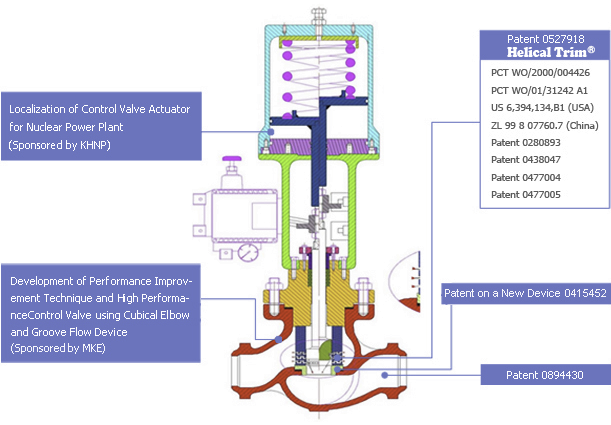
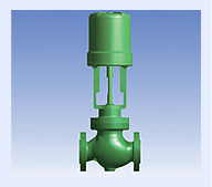
3D Multi-stage Trim Control Valve with Air-Operated ActuatorCertified Scope
Less than 20″, Less than 2,500 lbCharacteristics
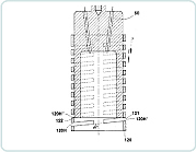
3D Multi-stage Trim control valve with air-operated actuator suitable to high pressure condition was developed using so unique technology in the world that Korea government certificated it as a ‘NEP’(New Excellent Product).- 3D Multi-stage Trim with three-dimensional and tortuous multi-flow paths structure using the latest patented technology
- flow velocity limiting and adjusting function of trim part (less than 23 m/sec.)
- precise linear control without flow dead band
- reduced noise level with consistent cross section over flow paths (less than 80 db)
- improved trim volume ratio for preventing valve from being damaged (less than 90%)
- reduced valve damage through the separation of flow regulating and sealing function (maintenance interval: 3 years, competitor’s products : 1~2 years)
Application
Power plant
|
Petrochemical plant
|
Applied Patented Technology
Design Technology
Trim Design
Parameters(Factors) for Trim Design- Loss coefficient for valve shape
- Loss coefficient due to trim
- Reynolds number
- Temperature, pressure and density of fluids
- Flow characteristics curve versus valve travel
- Fluid velocity
Design Considerations of Trim for High Differential Pressure Service(High Performance)
- Shape and size of valve
- Size of flow path and number of Stage
- Shape of flow path(resistance coefficient)
- Thickness of cylinder or disk
- Flow coefficient(Cv valve)

Limiting Valve for the Fluid Velocity(Energy)
| Condition Applied | Based on Kinetic Energy | Equivalent Velocity of Water | ||
|---|---|---|---|---|
| psi | kPa | ft/s | m/s | |
| Single Phase Fluid | 70 | 480 | 100 | 30 |
| Cavitation and Two Phase Fluid | 40 | 275 | 75 | 23 |
| Vibration-sensitive System | 11 | 75 | 40 | 12 |
Considerations for the Design(Selection) of Actuator
- Force due to the Fluid Pressure
- Weight of Plug
- Friction Force of Packing -Packing Material
- Spring Force
-Diameter of Stem
- Frictional Force of Balance Seal -Balance Seal Material
- Shutoff Force -Seat Leakage Class
-Diameter of Trim
-Diameter of Seat
Analysis Technology
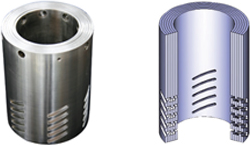
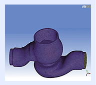
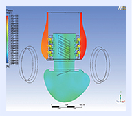
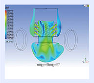
CFD Analysis
- Analyze fluid velocity, pressure and flow pattern at valve body, seat ring and trim using ANASYS CFX or FLUENT.
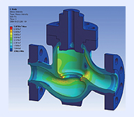
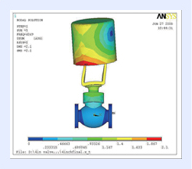
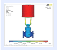
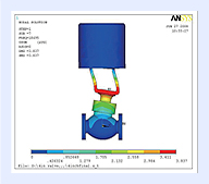
Structural Analysis
- Analyze the stress distribution due to operating load combination using ANSYS, NASTRAN and LS-DYNA, review the interference of components by calculating the displacement due to stress and validate the structural integrity and the design suitability based on the requirements of ASME and KEPIC.
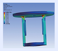
Seismic Analysis
- Perform the analysis to determine whether the natural frequency exceeds 33 Hz for kinds of materials of each component and for structural shape of control valve and validate the structural integrity against seismic load(Harmonic Analysis).
Testing & Qualification
Performance Qualification
- operability Test
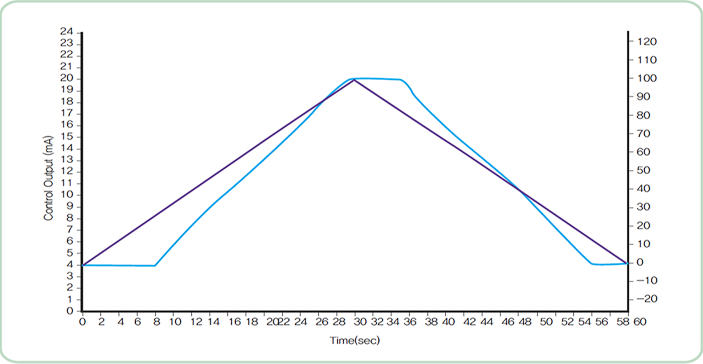
Elapsed Time vs. Valve Travel/Pressure
Control signal vs. Valve Travel
Equipment Qualification (ASME QME-1, IEEE 323, 344 and 382)
| Qualification Item | Test Condition and Method |
|---|---|
| Visual Inspection | Inspect appearance of equipment visually |
| Basic Performance Test | Acquiring basic research for equipment |
| Radiation Aging Test | 1.1X10⁴ Gy irradiation |
| Accelerated Thermal Aging Test | Validating the durability of equipment over forty(40) years Pressure Cycle Test |
| Pressure Cycle Test | Applying pressure of 65psig for fifteen(15) times |
| Vibration Aging Test | 5Hz~100Hz |
| Seismic Test | SSE, OBE |
| DBA Test | LOCA, MSLB, etc. |
Application
Seat Leakage Classification of Control Valve(ANSI B16.104)
| Leakage Class-Designation | Maximum Leakage Allowable | Test Medium | Test Pressure |
|---|---|---|---|
| Ⅰ | Reference value specified by user and manufacturer | - | As specified by manufacturer |
| Ⅱ | 0.5% of rated capacity | Air or Water at 10~52℃ | 45~60 psig or max. operation differential, whichever is lower |
| Ⅲ | 0.1% of rated capacity | As above | As above |
| Ⅳ | 0.01% of rated capacity | As above | As above |
| Ⅴ | 0.0005ml per minute of water per inch of port diameter per 1psi differential | Water at 10~52℃ | Max. rated differential pressure across valve plug |
Fluid Dynamic Change of Valve
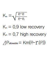
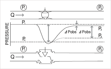
Difference of Pressure Recovery of Ball Valve and Globe Valve
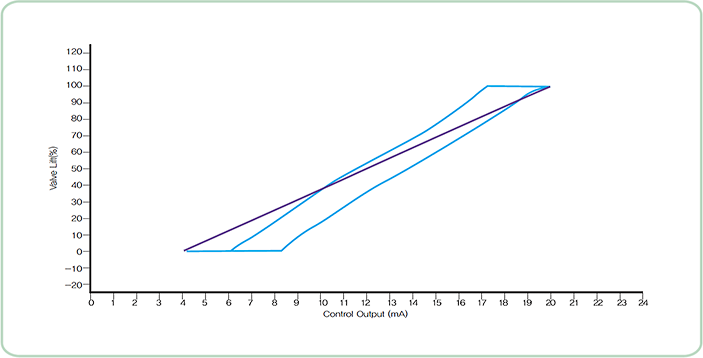
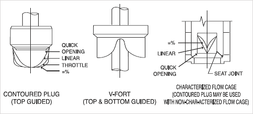
Flow Characteristics Curve and Trim Characteristics of Control Valve
Selection of optimum trim considering flow change due to pressure drop across valve and other piping component in control system.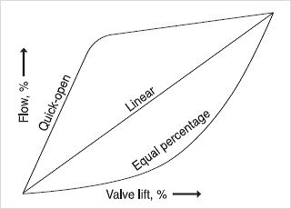
|
● Linear Flow Characteristic Flow rate is directly proportional to the amount of Valve Plug Travel
|
|
● Equal Percentage Characteristic For equal increments(%) of valve plug travel, equal percentage of the flow changes.
|
|
● Modified Parabolic Between Liner and Equal Percentage Precise throttled action at low flow and similar flow to Linear characteristic at high flow |
|
● Quick Open Characteristic Valve that needs quick opening
|
Retrofit & Up-Grade
|
Retrofit & Up-Grade(Grade) State of the art maintenance technique for improving the thermal efficiency due to leakage stoppage and the extension of life time and maintenance interval as well as the better performance(control ability, anti-erosion and corrosion and anti-leakage) than existing control valves through the redesign, repair and replacement of critical part(trim part) using hydro-dynamic technology |
Possible Targets for Retrofit & Up-Grade
|
Necessity of Retrofit & Up-Grade
|
Applicability of HARMONY Trim to Retrofit & Up-Grade
|
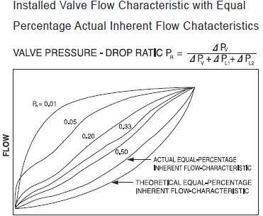
Application of Trim Characteristics Considering System
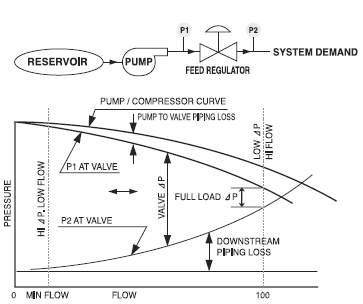
PERCENT FLOW-SYSTEM DEMAND
TRAVEL
Target for Performance Improvement
Power Plant Problem Valves
- MFWP & COP Recirculation valve
- HTR Drain Dump/Control valve
- Boiler(S/G) Pressure Control valve
- Main Steam Dump valve
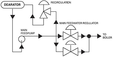
STARTUP FEEDWATER REGULATOR
Feedwater Control Valve Solutions
- Characterized Harmony Trim to eliminate cavitation and vibration
- Cylinder operator for high force loads for optimum control
- Flow to close design uses disk stack to protect critical guide and seating surfaces
Other Application
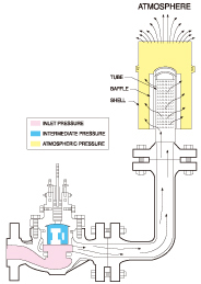
Noise reduction device in discharge side of the Pressure relief valve
Noise reduction by orifice or alternative design
Back-pressure device of the high pressure drop(Recirculation) valve
Integration of the overpressure protective and control function
Noise reduction by orifice or alternative design
Back-pressure device of the high pressure drop(Recirculation) valve
Integration of the overpressure protective and control function
Plasma Coating
|
Republic Korea Utility Model No. 20-415452 Title Valve Device Forming Carbon Ion Implantation Layer on Surface |
Characteristics
- Carbon ion implantation layer of uniform thickness is formed on the surface of part using the Plasma Source Ion Implantation(PSII) to strengthen the hardness, abrasion resistance and mechanical characteristics.
- Fluid leakage is prevented by protecting major valve components(trim part, plug, seat ring and cage) from the damage(erosion, corrosion, wear, galling and scratch) due to interaction of components and fluid kinetic energy occurred by differential pressure and high fluid velocity.
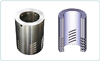
Pictures showing the Coating Application

General Product
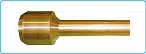
Product with Plasma Coating
Result of Coating Application
Part Condition |
Coating Thickness | Hardness(Hv) | Result |
|---|---|---|---|
| Stellite #6 | 2~3 mm | 75 | Steam cutting |
| Plasma Coating | 10μm | 2,000 | Nothing |